 Four-Faith IoT
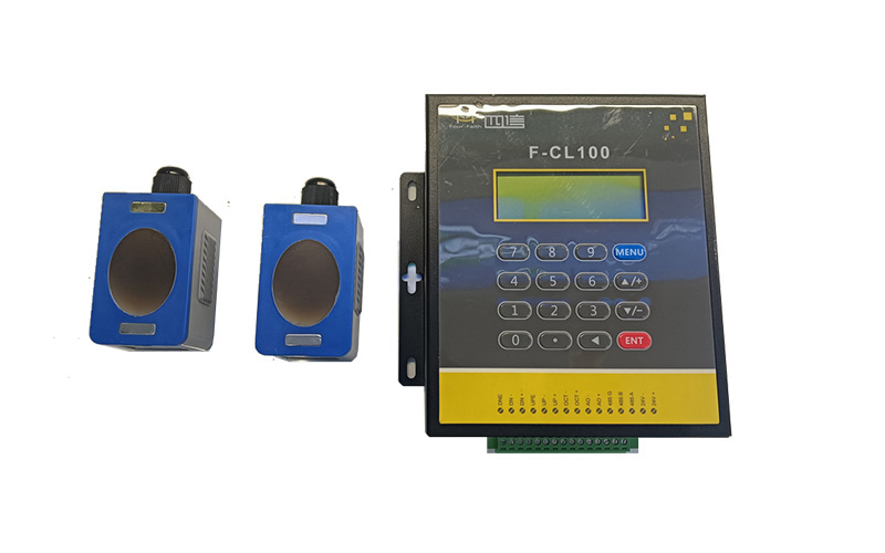
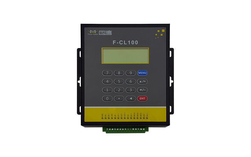
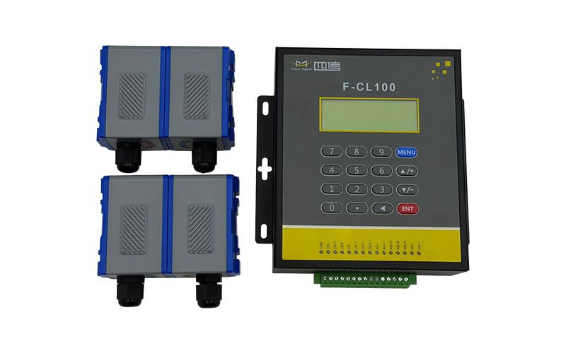
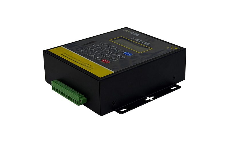
The system supports bidirectional velocity measurement and instantaneous/positive/negative/net flow tracking. When paired with a PT100, it records supply/return temperatures to calculate cumulative heat. It features low-flow zero-point suppression, multi-point linearity correction, and password-protected parameter locking. The local LCD cyclically displays measurement and diagnostic data, while a built-in clock automatically logs daily/monthly/annual totals and power events. A hardware watchdog ensures lost flow data is recalculated upon power restoration, and isolated RS485 Modbus communication allows parameter read/write.
The system supports various sensor types (clamp-on, standard/extended/parallel insertion, and pipe sections). Expansion capabilities include 4–20 mA analogue inputs (for temperature/pressure) and outputs, OCT pulses, relay alarms, an external thermal printer module, and local SD card storage.
The F-CL100 utilises the time-of-flight ultrasonic measurement principle and supports a choice of three sensor types—clamp-on, insertion and pipe-section—allowing bidirectional flow and heat measurement to be carried out without the need to cut or disrupt the pipeline. The modular main unit features multiple signal input and output interfaces, built-in high-capacity historical data storage and comprehensive self-diagnostic functions, and is suitable for a wide range of fluid types and pipe diameters. As installation and removal can be carried out without shutting down operations, it significantly reduces the costs associated with on-site construction, pipeline modifications and routine maintenance.
This ultrasonic flow meter supports clamp-on, insertion, and pipe-section sensors covering DN15 to DN6000, utilizing a time-difference algorithm with ≤0.5% linearity and ≤0.2% repeatability for bidirectional flow measurement. It is compatible with various sound-transmitting fluids and features extensive expansion interfaces, including 3 analogue inputs and dual PT100 connections for thermal energy metering. The system stores up to 512 days of historical data and supports batch retrieval. Designed for easy setup, it offers V/Z installation methods with dedicated distance calculators and real-time signal diagnostics. The IP67-rated main unit features fully hardware-isolated circuitry to resist EMI, wide-range AC/DC power supply, and an all-scenario O&M design with local magnetic button operation, remote parameter management, and multilingual interface support.
| Measurement parameters | Instantaneous velocity, instantaneous flow rate, positive/negative/net cumulative flow, supply and return water temperatures, instantaneous/cumulative heat | Velocity range | 0–±10 m/s, bidirectional measurement |
|---|---|---|---|
| Measurement accuracy | Flow rate ±1%, heat ±2%, repeatability 0.2% | Suitable pipe diameters | DN15–DN6000 |
| Suitable fluids | Water, seawater, acidic and alkaline solutions, alcohol, various homogeneous oils | Fluid temperature | Standard sensor – 30–90 °C; high-temperature version – 40–160 °C |
| Main unit power supply | DC 8–36 V / AC 85–264 V | Protection rating | Main unit protection rating: IP67; sensor protection rating: IP68 |
| Main unit operating environment | –20–60 °C, humidity < 85% (non-condensing) | Communication | Isolated RS485, supporting Modbus RTU/ASCII and M-BUS multi-protocol |
| Signal interfaces | 3 x 4–20 mA inputs; 1 x 4–20 mA output; 2 x OCT pulses; 1 x relay; 2 x PT100 temperature inputs | Storage | 512 days’ or 128 months’ flow records; 32 sets of power-on/off logs; optional SD card storage |
Water supply and drainage networks; industrial acid/alkali and oil transportation; heat metering for heating systems; sewage treatment; reservoir irrigation areas; flow monitoring of chemical fluid pipelines.
A Sand down the installation area of the pipeline to remove paint and rust, and apply a sufficient amount of coupling agent; calculate the standard installation spacing according to the menu, and fine-tune the probe position until the signal strength is ≥60 and the Q-value is ≥60; for large pipe diameters, prioritise the Z-method installation.
A Enable the low-flow cut-off function (recommended value: 0.03 m/s); perform zero-point calibration whilst the pipeline is full of water and at rest, then save the parameters; if necessary, input multi-point linear correction coefficients to eliminate system bias.
A Enable the power-off flow compensation function to automatically estimate the missing flow upon power-up; however, this is for reference only. For long-term stable measurement, it is recommended to ensure an uninterrupted power supply to the equipment and avoid frequent power cuts.
Send your project parameters, our engineers reply within 24 hours.
Get Free Quote