 Four-Faith IoT
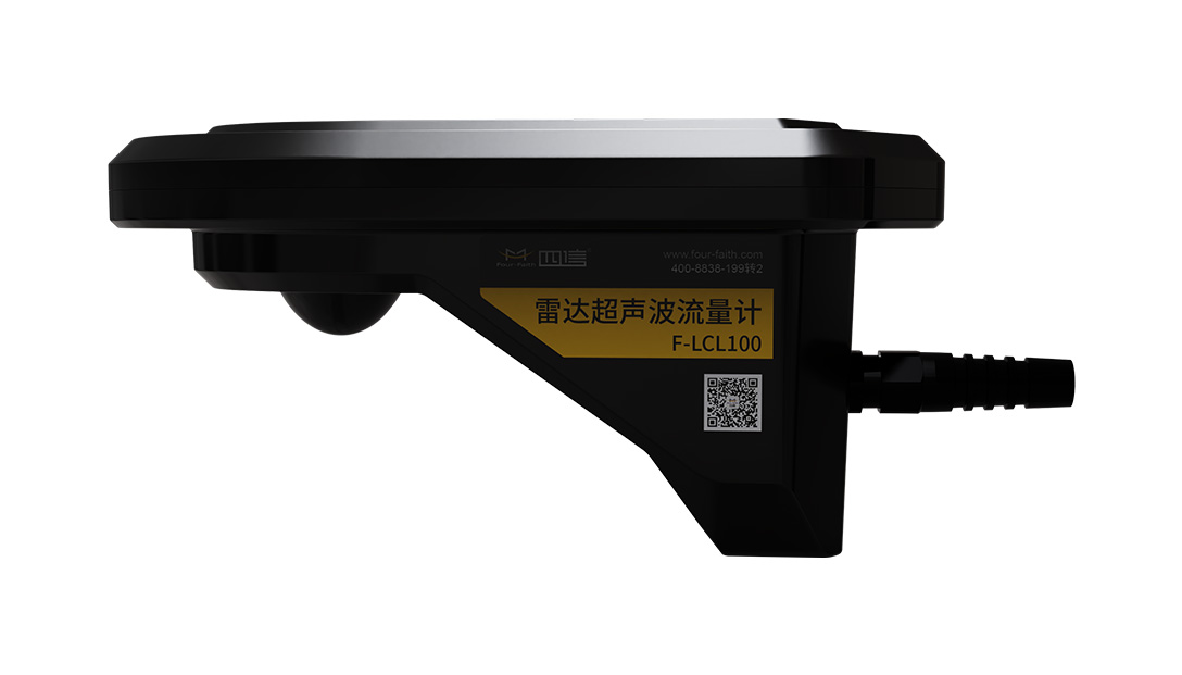
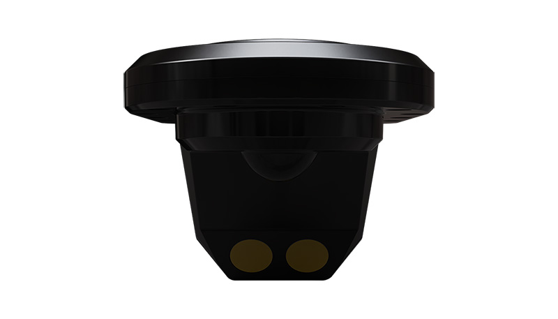
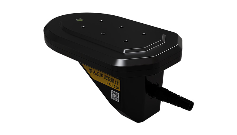
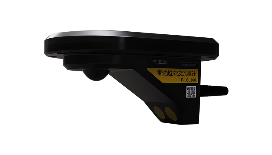
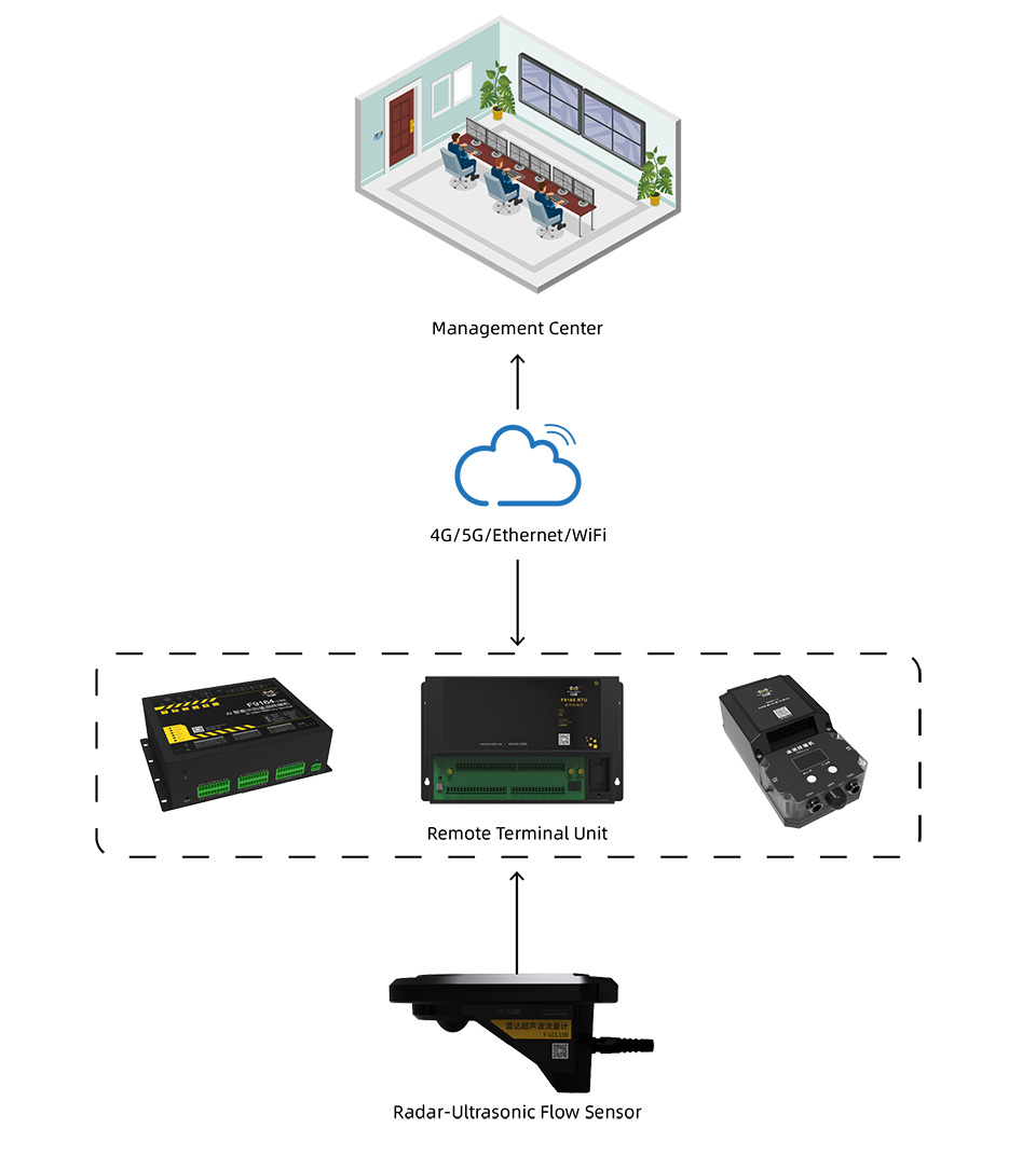
Automatic switching between radar and ultrasonic modes for flow velocity measurement; composite water level measurement via radar, hydrostatic pressure and conductivity; simultaneous acquisition of water temperature; built-in cross-section algorithms for automatic calculation of flow area, instantaneous flow rate and net cumulative flow; real-time transmission of device tilt angle, signal strength, free height and operational status; support for customisation of multiple cross-section parameters including rectangular, trapezoidal and circular;Modbus RTU for reading and writing device address, baud rate and filtering parameters; standard RS485 data output, with cable length extendable up to 200 metres.
No built-in expansion modules; compatible with on-site mounting brackets and shielded extension cables (to be purchased separately).
The F-LCL100 employs a dual-mode composite measurement solution combining radar and ultrasonic technology, coupled with multi-mode water level sensing via radar, static pressure and conductivity. It is suitable for monitoring flow in pipes, culverts and manholes under half-full / full-pipe flow monitoring under all operating conditions. With no mechanical moving parts, it automatically switches between non-contact radar and contact ultrasonic flow measurement modes. The built-in hydraulic model automatically converts instantaneous and cumulative flow rates. A single unit covers all scenarios from high to low water levels, significantly reducing the procurement costs associated with multiple sensors and the workload involved in regular cleaning and maintenance inside the well.
This composite sensor seamlessly measures flow velocity and water levels across full-pipe and half-pipe conditions without blind spots. Its impeller-free design prevents blockages from debris or silt, eliminating long-term manual cleaning. The system provides fully linear flow measurement without requiring K/C correction coefficients—simply enter cross-sectional parameters during installation. Housed in an IP68-rated, alloy-reinforced plastic enclosure, it resists corrosion and impacts in harsh underground environments. It features a fast 10-second response time with adjustable filtering to reduce noise, and offers simple top or wall mounting for stable data collection. Powered by a 12V DC supply, its low-power design is ideal for solar applications, while its standard Modbus interface ensures global compatibility with RTUs and cloud platforms.
| Measurement parameters | water velocity, water level, water temperature, instantaneous flow rate, net cumulative flow | Velocity range | 0.05–20 m/s |
|---|---|---|---|
| Velocity accuracy | Ultrasonic 1.0% ± 5 mm/s; Radar 2.0% ± 1 cm/s | Velocity resolution | 1 mm/s |
| Water level range | 0–10 m | Water level accuracy | 0.2% FS ±1 mm |
| Water level resolution | 1 mm | Water temperature range | 0–60 °C, accuracy 0.5 °C, resolution 0.1 °C |
| Interface type | 4-core shielded cable, RS485 communication interface | Communication protocol | Modbus RTU, default 9600 8N1 |
| Power supply and power consumption | DC 8–15 V (typically 12 V), total power consumption 150 mA @ 12 V | Protection rating | IP68 |
| Operating temperature | The documentation does not specify the operating temperature range for the unit separately | Radar flow velocity | 24 GHz; radar water level: 120 GHz; unit response time 10 s; the 485 cable can be extended up to 200 metres. |
Comprehensive water level and flow rate monitoring for urban underground box culverts, sewage culverts, municipal pipe networks, stormwater manholes and enclosed irrigation pipes
A A In a low-water half-pipe state, non-contact radar flow measurement is enabled; as the water level rises and the device becomes submerged, it automatically switches to contact ultrasonic flow measurement, with both sets of data used in conjunction to calculate the total flow rate.
A A The measurement curve is linear and free of deviation; it is only necessary to input the cross-sectional dimensions of the pipe or channel. Flow can be accurately calculated without the need to configure K or C correction curves.
A The device must be installed facing downwards and centred, with the beam directed towards the upstream flow; power and 485 communication must use separate shielded cables, and the communication cable can be extended up to 200 metres.
Send your project parameters, our engineers reply within 24 hours.
Get Free Quote